RVCR - tech R & D

RVCR technology is developed by GYATK through years of Research & Development.
They say necessity is the mother of invention, however this wasn’t the case here. RVCR was a result of the ability to thought experimenting with geometries, it assembly feasibility and design solutions. The idea was to develop a possible I.C. engine by using rotary pistons. This entire journey of ideating and conceptualization of the geometry and sequence of base components; were conceived by the inventor at the early stage. Later the timing methodology with cams for attaining the sequence and integration of gas and exchange accessories with their timing cams followed.
Once the concept was acknowledged in the IPER (International Preliminary Examination Report) by the EPO (European Patent office) against the PCT (Patent Corporation Treaty) application as true to Novelty, Inventive step, and Industrial applicability, the inventor initiated the project for the development of a prototype based on the RVCR concept.
This project lead to the development of the RVCR technology and the know-how and know-why for synthesizing kinetics for customized applications. The technology comprises, but not limited to, methodologies; techniques; formulas; information; designs; virtual & Analysis Methods and data; algorithms; manufacturing & QC processes; materials; testing; assembly & sub-assembly; strategies required for developing products based on the Principal of RVCR Mechanism.

The strategy
The approach to R&D project was a bottom-up one. It was the only way, as there didn’t exist design precedence of equivalent mechanism in use. Hence each individual component had to be designed from scratch which became the base of the pyramid and then build upwards to realize higher assemblies.
The engineering application selected for developing the 1st prototype was for an ‘I.C. Engine’, using the invented mechanism. The main reasons for the choice being: –
- The complexity and sophistication of ‘I.C. Engine Design’ process covers almost all subsystems used in other applications. Other products can be arrived by removing Sub-Systems for adapting the design for fast development of alternative products.
- I.C. Engines withstand extreme stress conditions and hence covers design sturdiness requirements of all other application Products.
A minimum viable proto specification was arrived at, and the criterions were
- To minimize the designing of components by using of standard ‘Of the Shelf’ accessories systems where-ever possible.
- The cubic capacity to match with a small size engine of a motorbike, for easy of handling, manufacture, and availability of operational data.
The Technology Constituent Modules are segregated for ease of design process management and customization for varying applications.
The Background
The spark moment happened to the inventor in his undergrade days while attending class on I.C.Engines. The slider-crank mechanism seemed cumbersome and the moment of ‘why not a rotating piston working against a stationary one’ happened.
The idea of getting two vanes, assembled in a concentric toroid was conceived. Slowly and steadily additional requirements were solved. The feasibilities of functionalities of 1st vane rotating and holding its counterpart the 2nd stationary till the 1st is to collide; the sequential turning, fitment of sealings and clutching etc.
These happened over a period of and was the result of inventor’s ability to perceive for 3D shapes and thought experimenting with it. The 1st wooden model was fabricated but the whole idea went into a cold box for a decade, though it always remained in the back of his mind.
Later the inventor by now employed on merchant ships marine engineer over the years, gained exposure to various engineering systems. The mercantile system inventor conceptualised newer possible geometries of parts, refining and modifying them to overcome assembling constraints and desired sequential motion etc. These exist in the schematic sketches of the 1st patent application made in India.
The Initial stage
This stage was self-financed and carried out inhouse. Each component virtual model was made in ideas software and assembled. These were checked for initial manufacture feasibility and feedback beginning with foundry (mould pattern makers), and later machining process tolerance were accommodated. Similar rounds of corrective iteration were made to improvise assembly, QC, testing concern.

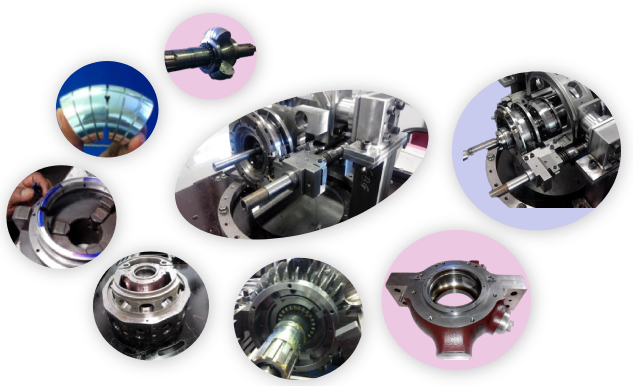
GYATK has perfected the root algorithms of the various critical sub-systems and their interdependencies that define the functional integrity of the RVCR Mechanism as a Fluid Handling Machine. The validation of these subsystems was carried out by physical manufacture of component systems and establishing the RVCR assembly to test the configuration.
The functional integrity of the Prototype assembly and essential sub-systems is validated through physical simulation of the thermodynamic gas process like compression, expansion, gas exchange, and air flow throughput. The mass manufacturability and longevity of components mainly the seals which have been a major issue for rotary Wankel engine is solved.
This saw the technological know-how for deriving pilot products for capability demonstration getting formulated. The project graduated into the phase of customising the knowhow for products.
Technology structure
The technology developed is structured in a ‘Tree table form’ where invented method is the ‘Root’ and core formulas form the ‘Trunk’, which are further customised for several ‘branches’ of applications. The genetic code of RVCR is in the patent which seeds ‘RVCR Ecosystem’.

RVCR Rotary positive displacement machine mechanism upgrades performance & efficiency parameters of all generic FHM including, I.C. engines, Pumps, Compressors & Motors at the same time reduces overall footprint, leading to new generation machines & fluid handling devices to shape future Energy Ecosystem.
The main Advantages of RVCR Mechanism originate from the “Variable Compression Ratio” (VCR) feature (ability to vary the Compression and Expansion Ratio).
‘Fluids are sucked-in and then pushed out of ‘FHM’ and used for Pumping or compressing them in Pumps and Compressors. In engines fluids (Fuel or Fuel/Air Mix) are sucked and compressed and burnt for powering other Machines, before it’s pushed out. Fluid flow Energy of wind or water is converted to rotational Power, when forced through FHM’
RVCR combines efficiency of ‘Positive Displacement’ in a compact of ‘Rotary’ unit and delivers VCR, which Crack-Opens Efficiency and Performance ceilings considered impossible with conventional mechanisms.
